


Subtrochanteric fracture location effect on surgical management using intermedullary nail (IMN) versus extramedullary plate (EMP): a finite element method analysis


Abstract
Background: Finite element method (FEM) analysis of the subtrochanteric fracture (STF) location effect in the subtrochanteric region (STR) fixated with the intermedullary nail (IMN) versus extramedullary plate (EMP) implant.
Material and methods: A femur computed tomography (CT) scan was used to create a femur FE-model with a straight-line fracture located at the STR. During the analysis, the fracture was stepwise lowered from 0.5 to 4.5 cm below the lesser trochanter (LT) with a total of 9 steps of 0.5 cm. The IMN (using proximal femoral nail antirotation) and EMP (using dynamic hip screw) implants were modelled and implemented for fracture management.
Results: EMP illustrated lower Von-Mises stress for the proximal fractures (until 3.5 cm below LT); whereas IMN showed lower stress for distal fractures (from 4 cm below LT). The mean Von-Mises stress ratio for IMN versus EMP also decreased from proximal (1.93) to distal (0.47) of STR, with an intersection cross-point at 3.8 cm below LT.
Conclusions: the simulation shows that for the straight-line STF, EMP seems more favourable for proximal and IMN is more likely favourable for distal fractures. However, more FEM studies need to be conducted (e.g., with different fractures or implant types) on this topic.
Citation
Daqiq O. Subtrochanteric fracture location effect on surgical management using intermedullary nail (IMN) versus extramedullary plate (EMP): a finite element method analysis. Eur J Transl Clin Med. 2024;7(1):22-32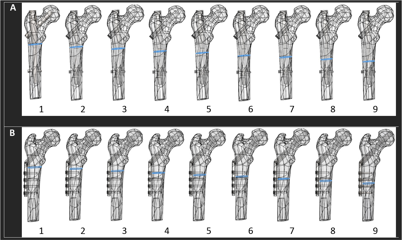


Introduction
Subtrochanteric fractures (STF) are defined as fractures of the proximal femur that occur within 5 cm of the lesser trochanter [1]. Approximately 5-10% of proximal femoral fractures occur in the subtrochanteric region (STR), with an estimated overall incidence of about 15-20 per 100,000 for STF [2-4]. In the Netherlands, it makes up 3-4 of annual hip fracture admissions [5], [6]. STF occurs mainly in older osteopenic patients after a low-energy fall or younger patients involved in high-energy trauma [1, 4, 7-8]. Roughly two-thirds of all STFs occur in patients over 50 years of age, with another 25% occurring in patients younger than 40 years old [1-2, 8-10]. Females suffer 2-3 times higher incidence compared to males [1, 11]. Risk factors such as low total hip bone mineral density, diabetes mellitus, and the use of bisphosphonate medications increase the probability of STF [1, 12-13].
Non-surgical treatments are associated with significant complications such as shortening and malrotation as well as an increase in prolonged immobilization, decubitus, and mortality [1, 14-15]. Surgical internal fixation leads to better bone healing and mobility recovery as well as reducing morbidity and preventing mortality [16]. The intermedullary nail (IMN) and the extramedullary plate (EMP) are one of the most common surgical methods used for STF management [17-24]. The effect of both implants has been studied in previous biomechanical studies (e.g., using simulation analysis) [25-28].
In the literature, there are uncertainties regarding STF management. Firstly, what is the effect of fracture location in the STR on fracture management? Secondly, does the fracture location in the STR justify the choice between IMN versus EMP implant? Therefore, this study aims to evaluate the impact of simple straight-line STF location in STR fixated by IMN versus EMP using the Finite Element Method (FEM) simulation analysis.
Material and methods
Femur model
A Computed Tomography (CT) scan (Siemens, SOMATOM Force model, Munich, Germany) of a normal cadaveric femur was used to generate a Digital Imaging and Communication in Medicine file (DICOM). The CT scan was made using the bone setting with a tube voltage of 90 kV, a tube current of 2.5 mA, and a matrix size 512x512. The 3D Slicer software (version 4, www.slicer.org) was used to create a three-dimensional (3D) femur model from the DICOM file and converted it to a Standard Triangle Language (STL) file. The femur STL-file was imported into Solidworks software (version 2014, 3D Modelling and Simulation, Waltham, Massachusetts, USA).
A straight-line fracture was created in the STR (the area from LT to 5 cm distal) (Figure 1). The fracture was then lowered from 0.5 to 4.5 cm below the LT, from proximal to distal, by steps of 5 mm with a total of 9 fracture locations (Figure 1). E.g., fracture 1 is located at the proximal section of STR and 0.5 cm below LT; fracture 9 is located at the distal section of STR and 4.5 cm below LT. The simple straight-line fracture was chosen for two reasons: (1) to optimally observe the effect of the two different implant systems used for the STF management, and (2) for an easier simulation of the fracture location effect in the STR concerning fracture management and fixation stability.
IMN and EMP model
Standard commercially available implants (DePuy Synthes, Raynham, MA, United State) were selected for the study. For the IMN, the proximal femoral nail antirotation (PFNA) was selected; and for the EMP, the dynamic hip screw (DHS). The implant fixation systems were 3D modelled in the Solidworks with identical mechanical material properties (Figure 1).
The PFNA implant (IMN) consisted of a short intramedullary nail, a lag screw, and a distal locking screw. The nail was 180 cm in length, with a target angle range of 135 degrees. The nail had a proximal diameter of 17.5 mm, where the lag screw was inserted for fixation inside the femoral head. The nail had a distal diameter of 11 mm, where the locking screw was inserted for fixation with femoral shaft. The lag screw was 90 mm in length and 12 mm in diameter. The distal locking screw had a diameter of 5 mm and a total length of 34 mm.
The DHS implant (EMP) consisted of a plate, a lag screw, and four screws. The plate had a thickness of 7 mm with a standard 38 mm barrel length in 135 degrees angle. The lag screw was 90 mm in length with a diameter of 12 mm. The four distal plate screws had a diameter of 5 mm and a total length of 38 mm.
Figure 1. (A and B, 1-9) Simple straight-line fracture located in the STR, lowered from proximal to distal region in 9 steps with a 5 mm distance between each step, starting from 0.5 cm to 4.5 cm below the LT; (A) STF fixated using the IMN (PFNA) and (B) the EMP (DHS) fixation.
DHS – dynamic hip screw, EMP – Extramedullary plate, LT – lesser trochanter, IMN – intermedullary Nail, PFNA – proximal femoral nail antirotation, STR – subtrochanteric region
FEM assembly
In the IMN (PFNA system) assembly: the nail was inserted inside the femur, with the lag screw positioned inside the femoral head, and the distal screw in the femoral shaft (Figure 1A). For the EMP (DHS system) assembly: the plate was positioned as close as possible to the femoral shaft, with the lag screw in the centre of the femoral head, and the four distal screws in the femoral shaft (Figure 1B). In both methods, the lag screw was positioned in the centre of the femoral head, and the distal screw(s) in the femoral shaft accordingly.
FEM simulation setup
Using Solidworks, a total of 18 assemblies were simulated, 9 assemblies used IMN (PFNA) (Figure 1A) and 9 EMP (DHS) (Figure 1B) fixation method.
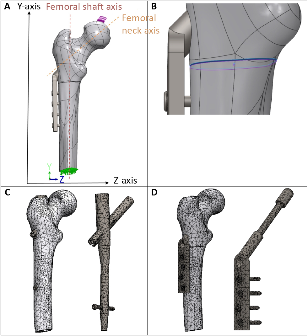
In each assembly, a force was applied at the femoral head downward in relation to the y-axis, representing the gravitational direction, at an angle of 8 degrees from the femoral neck axis (Figure 2A: illustration of applied force) [29-30]. During each analysis, the force was increased from 125 to 500 newton (N), replicating various body weights [31]. The femur was fixed at the femoral shaft using the Fixed Geometry option in the Solidworks (Figure 2A: illustration of the fixation).
The connection-option in the Solidworks provided the definition of the boundary conditions for the assemblies. Firstly, the fracture surfaces were defined by using the Contact-Sets option with 0.05 mm fixed distance with no penetration between the fracture surfaces, representing optimal fracture reduction (Figure 2B). When the fracture surfaces touch under application of load, there was no friction and only forces normal to the surfaces could be exchanged. Secondly, the Contact-Sets and the Component-Contacts option, was applied to define the interactions between the femur and the implants.
For the IMN fixation method, the proximal lag screw was set as fixed inside the femoral head, and the distal screw was set as fixed inside the formal shaft. Meaning that the intermedullary nail was held in a fixed position by the lag screw and the distal screw. The interaction between the nail and femur was set as contact. Furthermore, the nail, the lag screw, and the distal screw were set as fixed. Meaning, that the implant components (nail, lag screw, and distal screw) were modelled as one single piece.
For the EMP, the plate was placed as close as possible to the femoral shaft, and the plate barrel was set as contact inside the femur. The lag screw was set as fixed inside the femoral head, and the four distal plate screws were set as fixed inside the femoral shaft. Meaning, that the plate was held in a fixed position by the lag screw and the four distal screws. The interactions between the plate, the lag screw, and the four screws were set as fixed. This means that the whole implant (plate, lags crew, and distal screws) was set as one single piece.
The material properties of the femur were set at an elastic modulus of 14500 megapascal (MPa), shear modulus of 3280 MPa, mass density of 1180 kg/m3, tensile strength of 150 MPa, yield strength of 160 MPa, and Poisson’s ratio of 0.3 [32-33].
For the fixation implants, the material properties were set at an elastic modulus of 210000 MPa, shear modulus of 79000 MPa, mass density of 7700 kg/m3, tensile strength of 723.83 MPa, yield strength of 620.42 MPa, and Poisson’s ratio of 0.28 [34].
A curvature-based mesh was created with a maximum element size of 11.8 to 12 mm, a minimum element size of 2.3 to 2.4 and, an element size ratio of 1.6 (Figure 2C and 2D). Mesh dimensions were checked using the Mesh Quality Check option in Solidworks. Furthermore, the mesh size was decreased until the results were independent of the mesh size.
Figure 2. (A) Applied force on the femoral head (downward in the Y-axis or the gravitational force direction, 8 degrees from to the femoral neck axis); and applied fixture at the formal shaft. (B) Contact-Set of 0.05 mm distance with no penetration between the fracture surfaces. (C-D) Impression of the applied converged mesh for resp. the IMN (PFNA) and the EMP (DHS) assemblies.
DHS – dynamic hip screw, EMP – Extramedullary plate, LT – lesser trochanter, IMN – intermedullary Nail, PFNA – proximal femoral nail antirotation, STF – subtrochanteric fracture
Results
The FEM outcomes are represented in the form of the Von-Mises stress in the megapascal [MPa] unit (table 1), determining whether the assembly will yield or distort during the complex loading condition. The increase in force from 125 to 500 N resulted in a rise in the Von-Mises stress for both IMN (PFNA) and EMP (DHS) implants (Figure 3A and 3B). The analysis showed a linear relationship between the amount of force and the Von-Mises stress (Supplementary Figure 1).
Table 1. FEM von-Mises stress simulation results in MPa between PFNA versus DHS implants for 9 different fracture locations in STR
* Fracture locations in STR measured from the LT, lowered from proximal to distal region (from 0.5 to 4.5 cm below LT) in steps of 5 mm.
DHS – dynamic hip screw, FEM – finite element method, LT – lesser trochanter, MPa – megapascal, N – newton, PFNA – proximal femoral nail antirotation, STF – subtrochanteric fracture, STR – subtrochanteric region
Figure 3. Scatter plots representing the relationship between Von-Mises stress in MPa and STF location for (A) the IMN (using PFNA) and (B) the EMP (using DHS) implant. Hence: The STF location is based on the fracture distance below the LT in steps of 5 mm (e.g., location 1 is 0.5 cm and location 9 is 4.5 cm below LT).
DHS – dynamic hip screw, EMP – extramedullary plate, IMN – intermedullary nail, LT – lesser trochanter, MPa – megapascal, N – newton, PFNA – proximal femoral nail antirotation, STF – subtrochanteric fracture
IMN (PFNA) and STF location
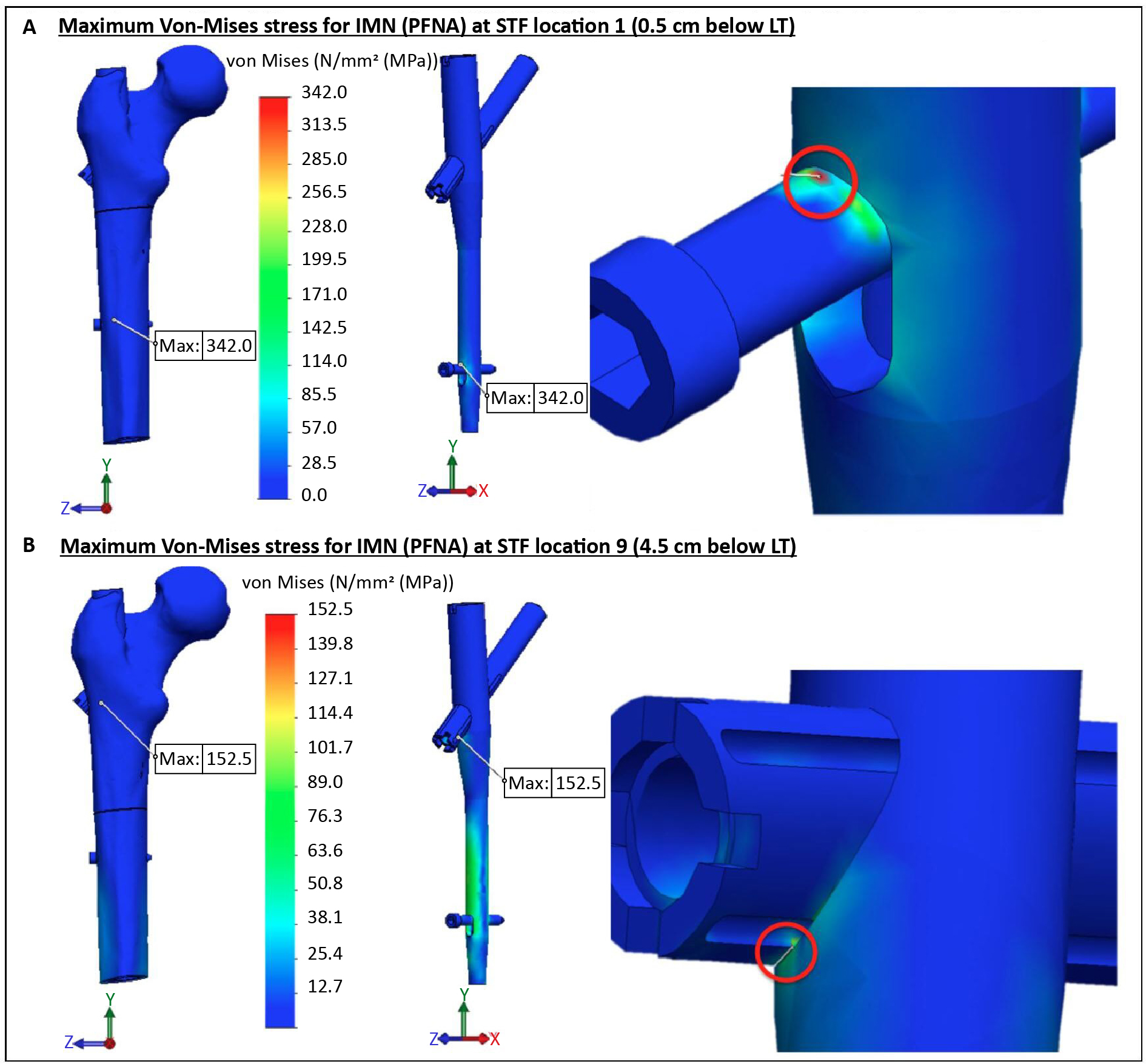
The IMN (using PFNA implant) analysis shows a decrease in the Von-Mises stress, when the fracture is lowered from proximal to distal of STR (Table 1). The location of the maximum Von-Mises stress remains similar for the fracture locations 1 to 8 (from 3.5 to 4.0 cm below LT), but changes for the fracture location 9. For the fracture locations 1 to 8: the maximum Von-Mises stress is at the upper border of the distal locking screw, where it touches the top side of the distal intramedullary nail hole (Figure 4A). For the fracture location 9: the maximum stress is located at the lag screw, mainly between the lower part of the lag screw and the proximal intramedullary nail hole (Figure 4B).
Figure 4. The Von-Mises stress distribution and the maximum stress position for the IMN (using PFNA) at the maximum force of 500 N: (A) the maximum stress at the STF location 1 (0.5 cm below LT), and (B) the maximum stress at the STF location 9 (4.5 cm below the LT).
IMN – intermedullary nail, LT – lesser trochanter, MPa – megapascal, N – newton, PFNA – proximal femoral nail antirotation, STF – subtrochanteric fracture
EMP (DHS) and STF location
The EMP (using a DHS implant) analysis generates an opposite result compared to the IMN (using a PFNA implant) outcomes. For the EMP analysis, the Von-Mises stress increases when the fracture is lowered in the STR from proximal to distal region (Table 1). The location of the maximum Von-Mises stress remains the same for all the fracture locations. The maximum stress is located on the distal plate screw, located at the upper contact point with the extramedullary plate (Figure 5A and 5B).
Figure 5. The Von-Mises stress distribution and maximum stress position for the EMP (using DHS) at the maximum force of 500 N: (A) the maximum stress at the STF location 1 (0.5 cm below LT), and (B) the maximum stress at the STF location 9 (4.5 cm below the LT).
DHS – dynamic hip screw, EMP – extramedullary plate, LT – lesser trochanter, MPa – megapascal, N – newton, STF - subtrochanteric fracture
Von-Mises stress ratio between IMN versus EMP
The mean Von-Mises stress ratio (for 125 to 500 N force) between the IMN (using a PFNA implant) versus the EMP (using a DHS implant) is shown in figure 6A. The ratio tends to gradually decrease when the fracture is lowered inside the STR from proximal to distal (resp. 1.93 at STF location 1 to 0.49 at location 9). The observation of the ratio shows that IMN (PFNA) stress is higher until STF location 7 (3.5 cm below LT). From fracture location 8 (from 4 cm below the LT), EMP (DHS) stress is higher compared to IMN (PFNA). The calculated intersection cross-point between the IMN versus the EMP (PFNA versus DHS) is 3.8 cm below LT (Figure 6B).
Figure 6. (A) The mean Von-Mises stress ratio (average stress ratio for 125 to 500 N forces) between the IMN versus the EMP (PFNA versus DHS) for the different STF locations. The equilibrium between the IMN and the EMP is reached at ratio 1 (at 3.8 cm below LT). (B) Illustrating mean Von-Mises stress (average stress between 125 to 500 N forces) intersection cross point between the IMN versus the EMP (PFNA versus DHS [3.8 cm below the LT]. Hence: The STF location is based on the fracture distance below the LT in steps of 5 mm (e.g., location 1 is 0.5 cm and location 9 is 4.5 cm below LT).
DHS – dynamic hip screw, EMP – extramedullary plate, IMN – intermedullary nail, LT – lesser trochanter, MPa – megapascal, N – newton, PFNA – proximal femoral nail antirotation, STF – subtrochanteric fracture
Discussion
The FEM study aimed to determine the effect of fracture location in STR for fracture management using the IMN (PFNA) versus the EMP (DHS) implants. The study illustrates that the IMN versus the EMP technique leads to different Von-Mises stress effects depending on the fracture location in STR.
The Von-Mises stress determines whether a material will yield when subjected to loading. It defines the threshold state of material between elastic and plastic or brittle failure deformations [36]. It combines the three principal stresses (in x-, y- and z-axis) into an equivalent stress. The stress is then compared to the yield stress property to judge the failure condition of the material. Therefore, the ratio between materials yield strength versus Von-Mises stress should remain greater or equal to one (ratio ≥ 1) to reduce the failure threshold and prevent assembly collapse [36, 37]. Based on the Von-Mises stress outcomes in this simulation study, the EMP (DHS) implant gives a more stable fracture management with a lower stress for the proximal STF’s (Figure 3B). For fractures located at the distal STR, the IMN (PFNA) implant tends to be the more suitable implant due to the lower Von-Mises stress (Figure 3A). The intersection cross-point for the mean Von-Mises stress (for 125 to 50 N) between the IMN and the EMP is 3.8 cm below the LT (Figure 6B). At this point, the effect of stress for the straight-line fracture in the STR changes, where above this level is the EMP implant suitable due to less stress, and the IMN implant seems more favourable below the point. Hence, in the analysis, the material properties, including the yield strength for the PFNA (IMN) and the DHS (EMP), are identical. The yield strength of implants is higher compared to the femur (resp. 620.42 to 160 MPa). In the study, the maximum stress remains on the implant parts and not the femur (Figures 4 and 5).
An important point to notice is that the applied force in the assembly has a linear relationship with the amount of stress for both IMN (PFNA) and EMP (DHS) (Supplementary Figure 1). Firstly, it is logical that a change in the load will have a linear effect on the amount of stress. Therefore, this linear relationship verifies that the simulation analysis is correctly executed. Secondly, an increase in load will eventually result in material failure. It seems that the proximal fractures can withstand more loading when using the EMP compared to the IMN; whereas for the distal fractures, the IMN can withstand more loading than the EMP before the failure threshold is reached (Figure 6B).
Furthermore, the maximum stress location differed between the IMN and the EMP implants. The EMP (DHS) implant gives the same maximum Von-Mises stress position for all the STF locations (Figure 5A and 5B). For the IMN (PFNA), the maximum stress position remains similar for the STF locations 1 to 8 (Figure 4A), but changes for the STR location 9 (Figure 4B). The changes in the maximum stress location for the IMN implant analysis can be explained by the biomechanical changes caused by different STF locations that result in changes in the magnitude and direction of forces and moments within the assembly. This effect is eliminated for the EMP (DHS plate) analysis because the DHS plate uses four distal screws in the femoral shaft instead of only one distal screw used in the PFNA nail system.
The study has a few limitations. First, implant configuration and placement must be done according to the fracture type; as well as weight-bearing should be adapted accordingly to the fracture type, implant type, and bone quality [37]. In the current study, the analysis is done based on a straightline fracture; therefore, other fracture types or configurations would generate different outcomes. The study uses a simple straight-line fracture which does not resemble a true traumatic fracture type in the STR. However, this fracture configuration was chosen for two reasons: (1) for an easier simulation of the fracture location effect in the STR concerning fracture management and fixation stability, and (2) to optimally observe the effect of the two different implant systems used for the STF management. In future studies, we recommend using different fracture types and configurations. Second, only PFNA and DHS (respectively as the IMN and the EMP fixation methods) were analysed since they are the most common implant of choice; however, other implant types or configurations (e.g., DCS) may produce different results. Third, the unphysiological applied force in the study does not resemble a true double leg stance, and different force congratulations will lead to different outcomes. Therefore, it would be wise to study the effect of different force configurations on this topic. Finally, the study makes use of the FEM computer simulation analysis where from one side it simplifies the clinical setting and gives a proper visual explanation regarding STF management based on various fracture locations in the STR. However, it only gives a suggestion regarding STF management. Therefore, future studies need to be conducted to analyse other fracture types, configurations, and implants. Furthermore, retro- or prospective clinical studies or laboratory (e.g., cadaveric, or polymeric mechanical testing) can be considered for clinical validation.
Conclusion
The subtrochanteric fracture location in the subtrochanteric region seems to have a major effect on the fracture stability. Furthermore, the required implant for the optimal subtrochanteric fracture stability (nail versus plate) can vary based on the different fracture configurations. However, this requires a substantial analysis to determine what type of an implant should be applied for what type of a subtrochanteric fracture location or configuration. Finally, the application of the finite element method seems to be a promising tool for the proximal femoral fractures management analysis.
Acknowledgment
None.
Conflict of interest
None.
Funding
None.
Supplementary material
The linear relationship between force and stress is represented in supplementary figure 1. Furthermore, the FEM setup and all the simulation outcomes are available online at https://ejtcm.gumed.edu.pl/articles/187180.
Attachments
References
| 1. |
Garrison I, Domingue G, Honeycutt MW. Subtrochanteric femur fractures: current review of management. EFORT Open Rev [Internet]. 2021;6(2):145-51. Available from: https://doi.org/10.1302/2058-5241.6.200048.
|
| 2. |
Jackson C, Tanios M, Ebraheim N. Management of Subtrochanteric Proximal Femur Fractures: A Review of Recent Literature. Adv Orthop [Internet]. 2018;2018:1-7. Available from: https://doi.org/10.1155/2018/1326701.
|
| 3. |
Ekström W, Németh G, Samnegård E, Dalen N, Tidermark J. Quality of life after a subtrochanteric fracture. Injury [Internet]. 2009;40(4):371-6. Available from: https://doi.org/10.1016/j.injury.2008.09.010.
|
| 4. |
Dhanwal DK, Dennison EM, Harvey NC, Cooper C. Epidemiology of hip fracture: Worldwide geographic variation. Indian J Orthop [Internet]. 2011;45(1):15-22. Available from: https://link.springer.com/10.4103/0019-5413.73656.
|
| 5. |
Kanis JA, Odén A, McCloskey E V., Johansson H, Wahl DA, Cooper C. A systematic review of hip fracture incidence and probability of fracture worldwide. Osteoporos Int [Internet]. 2012;23(9):2239-56. Available from: https://link.springer.com/10.1007/s00198-012-1964-3.
|
| 6. |
Zeelenberg ML, Van Lieshout EMM, Polinder S, Panneman MJM, Verhofstad MHJ, Den Hartog D. Trends in incidence, health care use and costs for subtrochanteric femur fractures in the Netherlands 2000–2019. Injury [Internet]. 2024;55(4):111461. Available from: https://linkinghub.elsevier.com/retrieve/pii/S0020138324001487.
|
| 7. |
Giannoudis P V., Ahmad MA, Mineo G V., Tosounidis TI, Calori GM, Kanakaris NK. Subtrochanteric fracture non-unions with implant failure managed with the “Diamond” concept. Injury [Internet]. 2013;44:S76-81. Available from: https://linkinghub.elsevier.com/retrieve/pii/S0020138313700172.
|
| 8. |
Bedi A, Toan Le T. Subtrochanteric femur fractures. Orthop Clin North Am [Internet]. 2004;35(4):473-83. Available from: https://doi.org/10.1016/j.ocl.2004.05.006.
|
| 9. |
Koval KJ, Rezaie N, Yoon RS. Subtrochanteric Femur Fractures. In: Proximal Femur Fractures [Internet]. Cham: Springer International Publishing; 2018. p. 101-12. Available from: http://link.springer.com/10.1007/978-3-319-64904-7_9.
|
| 10. |
Reiter MJ, Bui-Mansfield LT, O’Brien SD, Tubb CC. Subtrochanteric Femur Fractures. J Comput Assist Tomogr [Internet]. 2015;39(1):47-56. Available from: http://journals.lww.com/00004728-201501000-00009.
|
| 11. |
Ng AC, Drake MT, Clarke BL, Sems SA, Atkinson EJ, Achenbach SJ, et al. Trends in subtrochanteric, diaphyseal, and distal femur fractures, 1984–2007. Osteoporos Int [Internet]. 2012;23(6):1721-6. Available from: http://link.springer.com/10.1007/s00198-011-1777-9.
|
| 12. |
Jackson C, Tanios M, Ebraheim N. Management of Subtrochanteric Proximal Femur Fractures: A Review of Recent Literature. Adv Orthop. 2018;2018:1-7.
|
| 13. |
Napoli N, Schwartz A V., Palermo L, Jin JJ, Wustrack R, Cauley JA, et al. Risk Factors for Subtrochanteric and Diaphyseal Fractures: The Study of Osteoporotic Fractures. J Clin Endocrinol Metab [Internet]. 2013;98(2):659-67. Available from: https://academic.oup.com/jcem/article-lookup/doi/10.1210/jc.2012-1896.
|
| 14. |
Koval KJ, Rezaie N, Yoon RS. Subtrochanteric Femur Fractures. In: Egol KA, Leucht P, editors. Proximal Femur Fractures [Internet]. Cham: Springer International Publishing; 2018. p. 101-12. Available from: https://doi.org/10.1007/978-3-319-64904-7_9.
|
| 15. |
Barbosa de Toledo Lourenço PR, Pires RES. Subtrochanteric fractures of the femur: update. Rev Bras Ortop (English Ed [Internet]. 2016;51(3):246-53. Available from: https://linkinghub.elsevier.com/retrieve/pii/S225549711600046X.
|
| 16. |
Joglekar SB, Lindvall EM, Martirosian A. Contemporary Management of Subtrochanteric Fractures. Orthop Clin North Am [Internet]. 2015;46(1):21-35. Available from: https://linkinghub.elsevier.com/retrieve/pii/S0030589814001345.
|
| 17. |
Roberts CS, Nawab A, Wang M, Voor MJ, Seligson D. Second Generation Intramedullary Nailing of Subtrochanteric Femur Fractures: A Biomechanical Study of Fracture Site Motion. J Orthop Trauma [Internet]. 2002;16(4):231-8. Available from: http://journals.lww.com/00005131-200204000-00003.
|
| 18. |
Mittal R, Banerjee S. Proximal femoral fractures: Principles of management and review of literature. J Clin Orthop Trauma [Internet]. 2012;3(1):15-23. Available from: https://linkinghub.elsevier.com/retrieve/pii/S0976566212000124.
|
| 19. |
Wiss DA, Brien WW. Subtrochanteric Fractures of the Femur Results of Treatment by Interlocking Nailing. Clin Orthop Relat Res. 1992;283:231-6.
|
| 20. |
Massoud EIE. Fixation of subtrochanteric fractures. Strateg Trauma Limb Reconstr [Internet]. 2009;4(2):65-71. Available from: https://www.stlrjournal.com/doi/10.1007/s11751-009-0058-z.
|
| 21. |
Papp S, Backman C, Konikoff L, Tanuseputro P, Harley A, Shah S, et al. Comparing Intramedullary Nails Versus Dynamic Hip Screws in the Treatment of Intertrochanteric Hip Fractures on Post-operative Rehabilitation Outcomes:A Systematic Review Protocol. Geriatr Orthop Surg Rehabil [Internet]. 2022;13:215145932211441. Available from: http://journals.sagepub.com/doi/10.1177/21514593221144180.
|
| 22. |
Geetala R, Wakefield E, Bradshaw F, Zhang J, Krkovic M. Comparison of intra-operative outcomes following internal fixation with trochanteric stabilisation plate or intramedullary nail in intertrochanteric fractures. Eur J Orthop Surg Traumatol [Internet]. 2023;34(2):1193-9. Available from: https://link.springer.com/10.1007/s00590-023-03779-5.
|
| 23. |
Mirbolook A, Siavashi B, Jafarinezhad AE, Khajeh Jahromi S, Farahmand M, Roohi Rad M, et al. Subtrochanteric Fractures: Comparison of Proximal Femur Locking Plate and Intramedullary Locking Nail Fixation Outcome. Indian J Surg [Internet]. 2015;77(S3):795-8. Available from: http://link.springer.com/10.1007/s12262-013-1004-3.
|
| 24. |
Yoon Y-C, Kim J-W, Kim T-K, Oh C-W, Park K-H, Lee J-H. Comparative biomechanical analysis of reconstruction and cephalomedullary nails in the treatment of osteoporotic subtrochanteric fractures. Injury [Internet]. 2024;55(6):111512. Available from: https://linkinghub.elsevier.com/retrieve/pii/S0020138324001992.
|
| 25. |
Sowmianarayanan S, Chandrasekaran A, Kumar RK. Finite element analysis of a subtrochanteric fractured femur with dynamic hip screw, dynamic condylar screw, and proximal femur nail implants — a comparative study. Proc Inst Mech Eng Part H J Eng Med [Internet]. 2008;222(1):117-27. Available from: http://journals.sagepub.com/doi/10.1243/09544119JEIM156.
|
| 26. |
Wang L, Zhao F, Han J, Wang C, Fan Y. Biomechanical study on proximal femoral nail antirotation (PFNA) for intertrochanteric fracture. J Mech Med Biol [Internet]. 2012;12(04):1250075. Available from: https://www.worldscientific.com/doi/abs/10.1142/S0219519412005125.
|
| 27. |
Wang J, Ma J-X, Lu B, Bai H-H, Wang Y, Ma X-L. Comparative finite element analysis of three implants fixing stable and unstable subtrochanteric femoral fractures: Proximal Femoral Nail Antirotation (PFNA), Proximal Femoral Locking Plate (PFLP), and Reverse Less Invasive Stabilization System (LISS). Orthop Traumatol Surg Res [Internet]. 2020;106(1):95-101. Available from: https://doi.org/10.1016/j.otsr.2019.04.027.
|
| 28. |
Yu B. Proximal Femoral Nail vs. Dynamic Hip Screw in Treatment of Intertrochanteric Fractures: A Meta-Analysis. Med Sci Monit [Internet]. 2014;20:1628–33. Available from: http://www.medscimonit.com/abstract/index/idArt/890962.
|
| 29. |
Carey T, Key C, Oliver D, Biega T, Bojescul J. Prevalence of Radiographic Findings Consistent With Femoroacetabular Impingement in Military Personnel With Femoral Neck Stress Fractures. J Surg Orthop Adv [Internet]. 2013;22(01):54-8. Available from: http://www.datatrace.com/e-chemtracts/emailurl.html?http://www.newslettersonline.com/user/user.fas/s=563/fp=20/tp=37?T=open_article,50067469&P=article.
|
| 30. |
Kazemi SM, Qoreishy M, Keipourfard A, Sajjadi MM, Shokraneh S. Effects of Hip Geometry on Fracture Patterns of Proximal Femur. Arch bone Jt Surg [Internet]. 2016;4(3):248-52. Available from: http://www.ncbi.nlm.nih.gov/pubmed/27517071.
|
| 31. |
Konstantinidis L, Papaioannou C, Hirschmüller A, Pavlidis T, Schroeter S, Südkamp NP, et al. Intramedullary nailing of trochanteric fractures: central or caudal positioning of the load carrier? A biomechanical comparative study on cadaver bones. Injury [Internet]. 2013;44(6):784-90. Available from: https://linkinghub.elsevier.com/retrieve/pii/S0020138313000053.
|
| 32. |
Wirtz DC, Schiffers N, Pandorf T, Radermacher K, Weichert D, Forst R. Critical evaluation of known bone material properties to realize anisotropic FE-simulation of the proximal femur. J Biomech [Internet]. 2000;33(10):1325-30. Available from: https://linkinghub.elsevier.com/retrieve/pii/S0021929000000695.
|
| 33. |
Cristofolini L, Taddei F, Baleani M, Baruffaldi F, Stea S, Viceconti M. Multiscale investigation of the functional properties of the human femur. Philos Trans R Soc A Math Phys Eng Sci [Internet]. 2008 Sep 28;366(1879):3319-41. Available from: https://royalsocietypublishing.org/doi/10.1098/rsta.2008.0077.
|
| 34. |
Implant Materials. Wrought 18 % Chromium – [Internet]. 3rd ed. Synthes; 2009. Available from: https://silo.tips/download/third-edition-implant-materials-wrought-18-chromium-14-nickel-25-molybdenum-stai#.
|
| 35. |
Yu M, Li J, Ma G, editors. Yield Condition BT. In: Structural Plasticity: Limit, Shakedown and Dynamic Plastic Analyses of Structures [Internet]. Berlin, Heidelberg: Springer Berlin Heidelberg; 2009. p. 32-63. Available from: https://doi.org/10.1007/978-3-540-88152-0_3.
|
| 36. |
Bai Q, Bai Y. Thermal Expansion Design. In: Subsea Pipeline Design, Analysis, and Installation [Internet]. Elsevier; 2014. p. 187-220. Available from: https://linkinghub.elsevier.com/retrieve/pii/B9780123868886000092.
|
| 37. |
Burnei C, Popescu G, Barbu D, Capraru F. Intramedullary osteosynthesis versus plate osteosynthesis in subtrochanteric fractures. J Med Life [Internet]. 2011;4(4):324-9. Available from: http://www.ncbi.nlm.nih.gov/pubmed/22514563.
|
