
Optimisation of osteosynthesis positioning in mandibular body fracture management using finite element analysis


Abstract
Background: This proof of principle study aims to investigate the applicability of finite element analysis (FEA) in Oral and Maxillofacial (OMF) surgery, by studying the effect of mandibular body height and osteosynthesis positioning on unilateral mandibular body fractures based on Champy’s technique.
Material and methods: Mandibles made of polyurethane foam (Synbone®), with heights of 18, 14, and 10 mm were used to create a FEA model with a unilateral straight-line fracture, fixated with a standard commercially available 6-hole 2 mm titanium miniplate. Two different FEA programs were used for the comparison, namely: Solidworks and Comsol Multiphysics. The FEA outcomes were compared with a series of mechanical tests with polymeric models fixed in a customised device and loaded onto a mechanical test bench.
Results: First, the study illustrated that the optimal plate position appeared to be the upper border. Second, lower mandibular height increases instability and requires a stronger osteosynthesis system.
Conclusions: FEA’s and polymeric model testing outcomes of unilateral non-comminuted fractures were highly comparable with current opinions of mandibular fracture management. The promising outcome of this study makes it worthwhile to do more extensive analysis in order to determine whether FEA alone is sufficient for optimisation of fracture management.
Citation
Daqiq O, Roossien C C, Wubs F W, Bos R R, van Minnen B. Optimisation of osteosynthesis positioning in mandibular body fracture management using finite element analysis. Eur J Transl Clin Med. 2023;6(2):10-25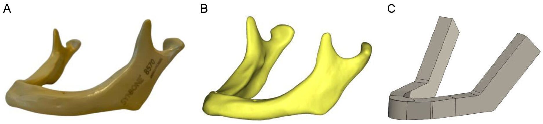


Introduction
Osteosynthesis plates and screws are routinely used in oral and maxillofacial (OMF) surgery [1-5]. In OMF surgery, mandibular fracture management is based on two completely different principles: (1) the osteosynthesis plate must provide enough rigidity to avoid fragment displacement during functional movement achieved through rigid fixation by placing solid plates at the lower border (load-bearing principle), and (2) the Champy technique suggesting the use of semi-rigid fixation with miniplates in which the tensile forces are neutralized by placing the plates in the so-called ideal line of osteosynthesis, resulting in interfragmentary stability between the bone segments (load-sharing principle) [6-8].
The applied (mastication) forces on the mandible cause different tension and compression zones [9]. The mandibular body’s upper border is a tension zone, whereas the lower border is a compression zone [8-9]. According to current clinical understanding and literature, a decrease in mandibular body height in an atrophic mandible results in a narrow range between the tension and compression zones [10-13]. In a severely atrophic mandible, the tension and compression zones more or less overlap each other and the load-sharing principle is not valid anymore [6-8, 14-15].
Following Champy’s theory, many studies started using expensive and time-consuming cadaveric or polymeric bone models [16-19]. It could be beneficial to use three-dimensional (3D) modelling and finite element analysis (FEA) instead of model testing. FEA is a non-invasive computational method to evaluate the stress distribution and displacement within a structure on load application [20-21]. It is a reliable and accurate numerical simulation tool for studying force distribution in the OMF area [21-22]. FEA enables the studying of mandibular fracture fixation, possibly leading to solutions regarding plate positioning and predicting the consequences of mandibular height decrease [23-26]. So far, the use of FEA to address clinical issues has been limited. In OMF surgery, not every issue regarding the best possible osteosynthesis has been resolved, e.g. complex comminuted fractures or extremely atrophic mandibles [14-15]. As these cases are less common than non-complex fractures, any subsequent clinical studies are very time-consuming or impossible without the required inclusions [15, 27]. Therefore, there is a need for a validated three-dimensional (3D) computer modelling and FEA simulation method to analyse these fractures and to plan the best osteosynthesis system for each clinical scenario, possibly by introducing new implants (e.g. degradable or patient-specific 3D printed plates) [23].
Hence, the purpose of our study was to compare mandibular model testing with FEA as a first step towards developing a validated 3D computer model for optimising mandibular fracture management. As proof of principle, we studied the effect of plate positioning and the effect of reduced mandibular body height in mandibular body fracture management based on the FEA simulations. In this initial study, the model was simplified by using mandibles with a unilateral straight-line body fracture only. Our first hypothesis was that the clinical observations of plate positioning and its effect on fracture stability, according to the load-bearing versus load-sharing principles, are reproducible in the 3D computer model. The second hypothesis was that the 3D computer model will confirm the theory that a reduction in atrophic mandible height leads to a decrease in interfragmentary stability making load-bearing fixation necessary. Finally, we hypothesized that FEA is a suitable tool to facilitate the visualisation of fixation stability which may subsequently help the surgeon in selecting an appropriate osteosynthesis system and in positioning the plate correctly.
Material and methods
Study design
We used FEA to analyse the effect of plate positioning for different mandibular body heights with a unilateral mandibular body fracture. The FEA simulations were conducted primarily in the computer simulation software Solidworks version SP5.0, 2020, 3D Modelling and Simulation, Waltham, Massachusetts, USA). The eligibility, reproducibility and accuracy of the outcomes generated in Solidworks were compared with those from a second simulation software Comsol Multiphysics (version 5.5, 3D Modelling and Simulation, Stockholm, Sweden). Further validation was done by comparing the results with a series of polymeric models fixated in a customized device on a mechanical test bench (DYNA-MESS Prüfsysteme, Stolberg, Germany). All the mandibles were fixated with the same type of osteosynthesis system (2.0 mm titanium miniplates, KLS Martin Group, Tuttlingen, Germany) and identical simulations were conducted for each study.
Assembly modelling
Synbone (Zizers, Switzerland) mandibles with body heights of 18, 14, and 10 mm (representing the slightly, moderately and severely atrophic mandibles, respectively) were used to create the 3D computer models of the mandible. Cone beam computed tomography (CBCT) (Planmeca, Promax 3D Max ProFace, Helsinki, Finland) was conducted on each Synbone mandible and digital imaging and communication in medicine (DICOM) files were generated. The CBCT scans were made at the bone setting with a voxel size of 400 µm, tube current of 2.5 mA, and tube voltage of 120 kV. DICOM files were used for the 3D modelling of the mandibles. The 3D computer modelling dimension measurements were performed using the Mimics software (version 25.0, Materialise, Leuven, Belgium). The 3D mandible models were then created in Solidworks after which they were geometrically simplified to eliminate mesh errors and simplify the simulation computations (Figure 1). In the study, the same type of straight-line unilateral mandibular body fracture was applied to each model. The distance between the fracture surfaces was set at 0.1 mm. The fracture type, size, and placement were identical in all the 3D models. The fracture was placed in the middle of the mandibular body, in between the first molar and second premolar. A standard commercially available 6-hole 2 mm osteosynthesis titanium miniplate (KLS Martin Group, Tuttlingen, Germany) with a length of 36.3 mm and 6 x 2 mm diameter screws with a length of 18.4 mm were modelled in Solidworks. The 6-hole miniplate was used for all the FEA computer simulation analyses (Figure 2).
Figure 1. 3D computer modelling of the mandible: (A) Synbone® mandible, (B) DICOM file from CBCT, and (C) a simplified 3D model of a mandible
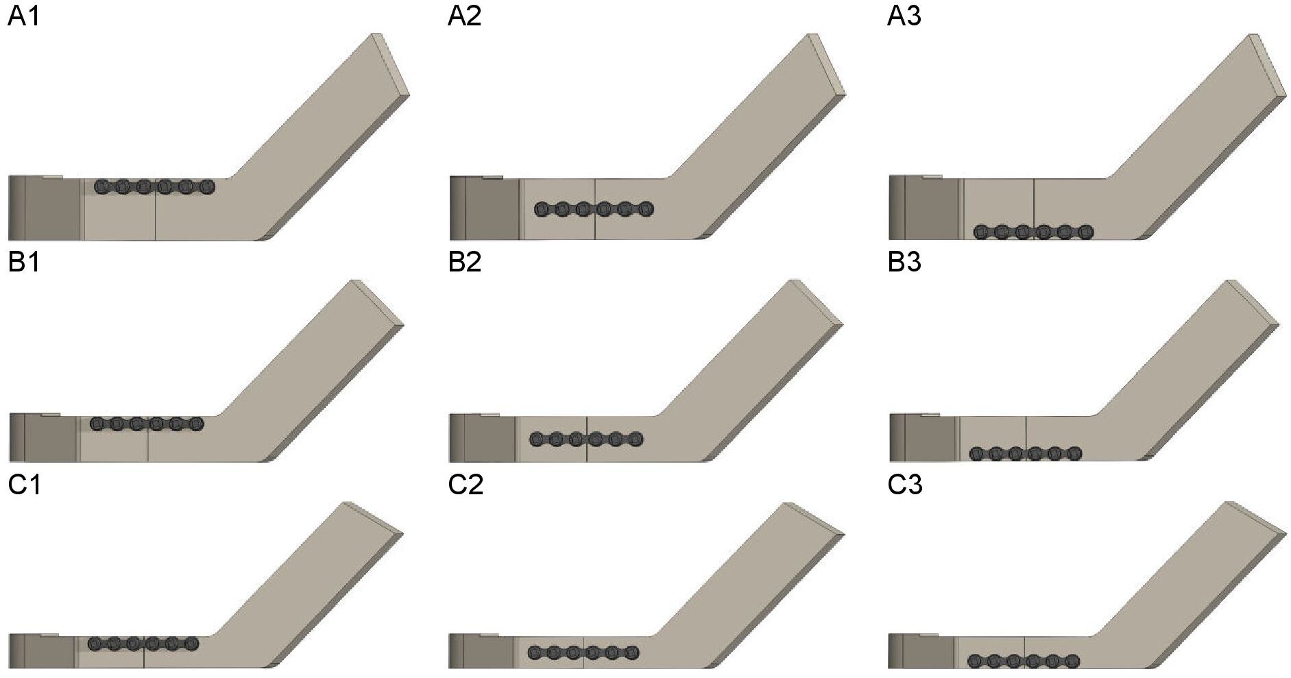
Figure 2. Plate positioning at the (A) 18 mm, (B) 14 mm, and (C) 10 mm mandibular body heights: (1) miniplate positioned at the upper border, (2) in the middle, and (3) at the lower border of the mandible
FEA Solidworks
FEA was primarily performed in the Solidworks software. The analysis started with positioning the osteosynthesis miniplate at the mandible’s upper border and subsequently lowering it towards the lower border along the fracture line. This was done to determine the effect of plate positioning at different mandibular body heights (Figure 2). Plate positions 1 to 3 represent the miniplate at the upper border, in the middle, and at the lower border of the mandible, respectively.
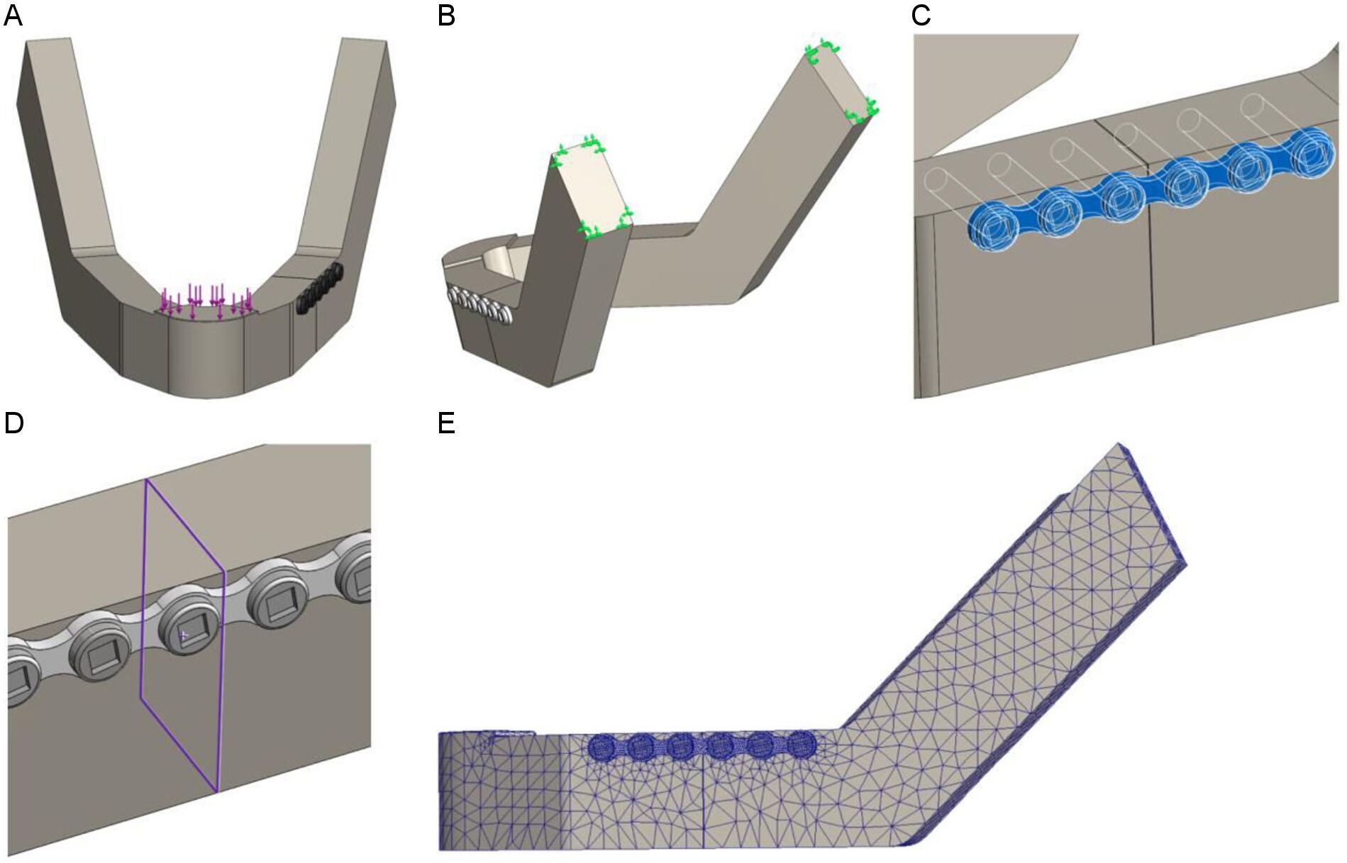
The average mastication force (200 N) was applied downward on the symphysis of the mandible (Figure 3A) [28-29]. The mandibles were fixed at the condylar head to replicate the temporomandibular joint by applying the fixed geometry option from the Solidworks fixture property manager tab (Figure 3B). Furthermore, the effect of fixation site was evaluated by conducting a series of sensitivity tests for different fixation locations (Supplementary Figure S1).
The chosen mandible material properties were similar to those of the Synbone® polyurethane foam mandible to allow for a comparison with polymeric model testing. The mandible material properties were set at an elastic modulus of 2410 MPa, shear modulus of 862.2 MPa, mass density of 1.26 g/cm3, tensile strength of 40 MPa, and a Poisson’s ratio of 0.39 [30-32].The properties of the titanium miniplates and screws were as follows: an elastic modulus of 104800 MPa, mass density of 4.43 g/cm3 , tensile strength of 1100 MPa, yield strength of 827.4 MPa, and a Poisson’s ratio of 0.31 [1]. Using the Solidworks contact-sets property manager tab we defined the boundary conditions between the mandibles, miniplates, and screws (Figure 3C). The connection between the two fracture surfaces was defined by using the contact-sets with a fixed distance of 0.1 mm between the fracture surfaces (Figure 3D), representing optimal fracture reduction. When the fracture surfaces touch, only the forces normal to the surfaces would be exchanged and there was no friction force present. The mandible screw holes and the screws were set as bounded, meaning that the screws were fixed tightly in the mandible, pressing the plate against the mandibular body. The connection between the miniplate and the screws, as well as the connection between the miniplate and the mandible, were set using the contact option from the contact-sets property manager. Only normal forces and no friction were present here, which is in accordance with the current opinion on stabilising mandibular fractures using non-locking plates. The boundary conditions and parameters were identical in all of the FEA studies.
FEA Comsol
Comsol was used to verify the Solidworks results and to evaluate whether the outcomes were reproducible, reliable, and accurate. The 3D computer model assemblies of each mandible and the osteosynthesis miniplate were imported from Solidworks in STEP file format. The imported assemblies were processed and saved in the Comsol 3D environment. All the FEA inputs were performed identically as in Solidworks. A force of 200 N was applied downwards on the symphysis of the mandible and fixation was set at the condylar head. The connections between the miniplate and the screws, as well as between the miniplate and the mandible, were set using the contact constraint option. The connection between the mandible and the screws was set as fixed using the continuity constraint option. The applied mesh was similar to the one in Solidworks.
FEA mesh convergence
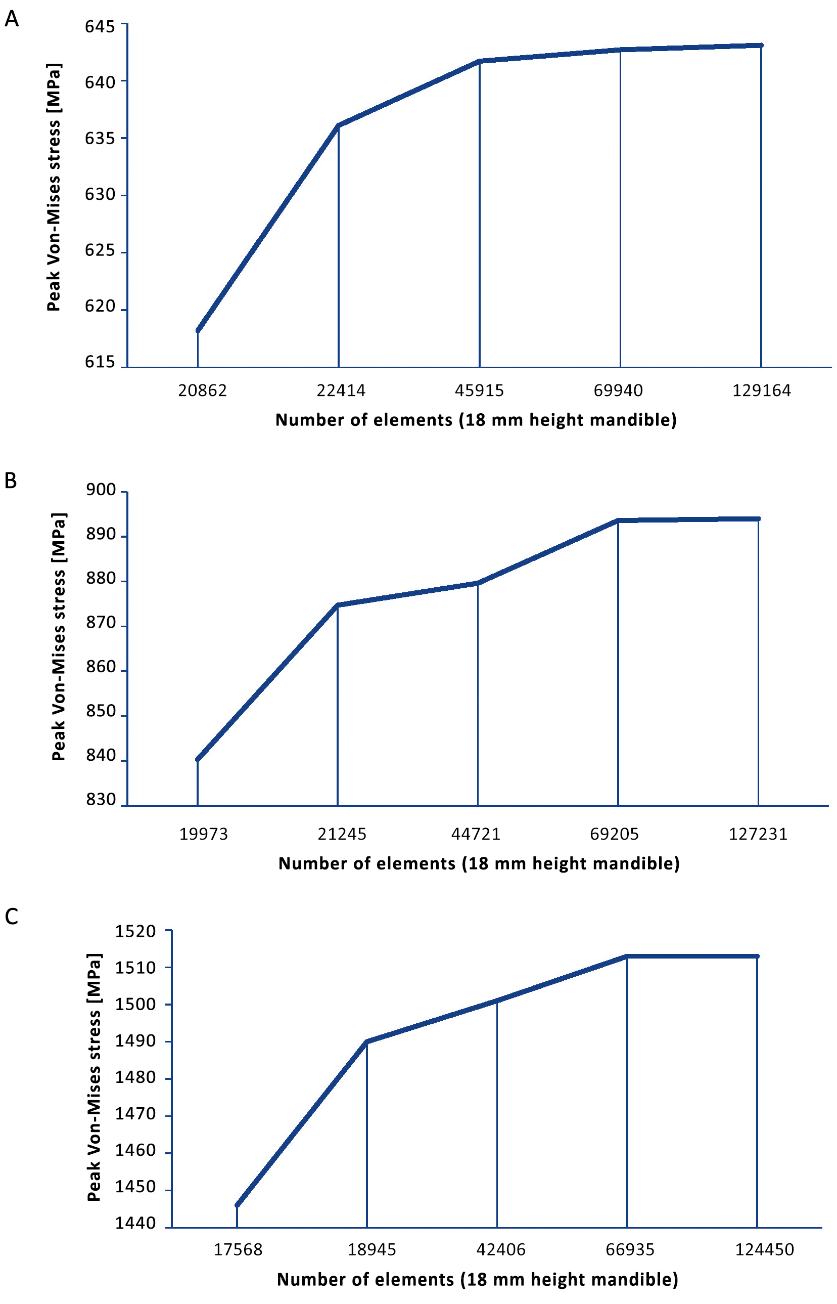
The chosen mesh dimensions were checked in the simulation models to determine whether they were correct. The mesh size was reduced until the results were independent of the mesh size and mesh convergence was reached (Supplementary Figure S2). The converged mesh was used for the remaining FEA studies (Figure 3E). The mesh applied in Solidworks was similar to the mesh in Comsol.
Figure 3. FEA set up in Solidworks: (A) Mastication force of 200 N is applied downward on the symphysis, (B) Fixation at the condylar head, (C) Contact boundary condition between the mandible and osteosynthesis system, (D) Contact-set boundaries between the fracture surfaces with a fracture distance of 0.1 mm and no penetration, and (E) Impression of the used mesh.
Polymeric model testing
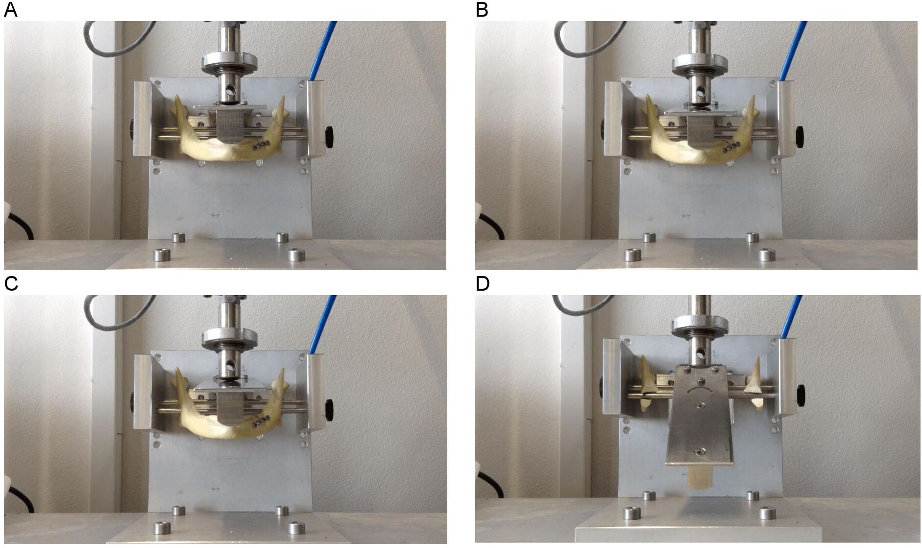
A polymeric mandible is made of polyurethane foam and is an adequate substitute for cadaveric human bone for testing purposes [30-32]. It has been shown to be a successful simulator for a similar sized and shaped human bone [30, 33‑34]. Polymeric model testing was conducted on a mechanical test bench to validate the FEA. Polymeric mandible replicas with body heights of 18, 14, and 10 mm were obtained from Synbone. A straight-line unilateral fracture was applied to each mandibular body and fixated with the osteosynthesis miniplate system. Polymeric model testing of 18 and 14 mm mandibular heights entailed using a 4-hole miniplate with four screws. A 6-hole miniplate with six screws was used for the 10 mm mandibular height. Only the osteosynthesis miniplates positioned at the upper border of the mandible were tested. Each of the three polymeric mandible replicas (the 18, 14 and 10 mm heights) was tested three times. A custom device was built to position the mandibles on the mechanical test bench (Figure 4). A load representing the mastication force was applied to the mandible and gradually increased at a rate of 10 N/s (Figure 4A). The values were set in the computer system of the mechanical test bench. The force on the mandible was increased continuously until the failure point where the mandible breaks down was reached (Figure 4D). Computerised sensors on the mechanical test bench recorded the data. All three mandible heights were tested using the same technique.
Figure 4. Mandible (with straight-line fracture and miniplate fixation) positioned on the custom-made device and loaded in a mechanical test bench; the starting point is (A) until it reaches the breaking point (D)
Data analysis
The FEA Solidworks outcomes were compared with the Comsol outcomes. This was done by first measuring the amount and the location of the maximum Von-Mises stress (Figure 7A-B). Then the displacement in the Z-axis was compared (Figure 7C-D). Finally, the Von-Mises stress pattern at a selected stress point was compared between the two FEA studies (Figure 6). The FEA outcomes were also compared with the polymeric model testing by observing the displacement patterns of the miniplates positioned at the upper borders of the mandibles with the different fracture heights (Figure 8). The displacement in the Z-axis of the FEA was used for the comparisons with the displacement in the polymeric model testing. Finally, data were evaluated with help of experts in statistics, however due to the small sample size statistical analysis did not make sense in this study.
Results
FEA Solidworks
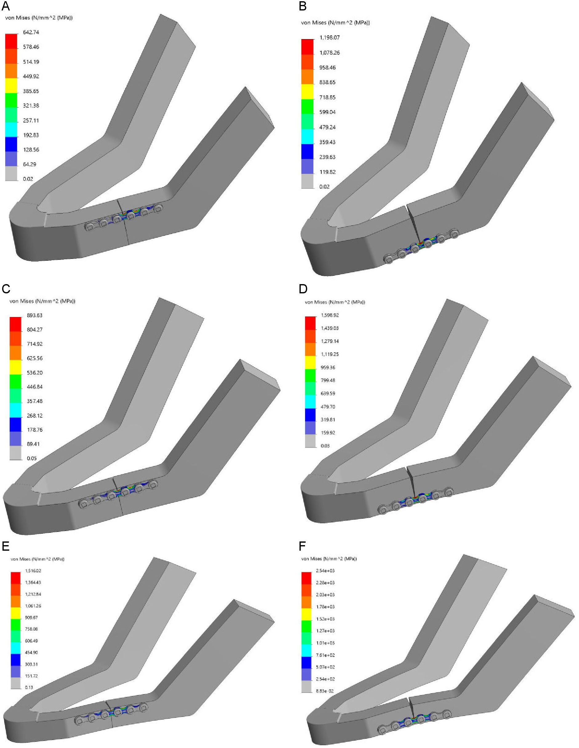
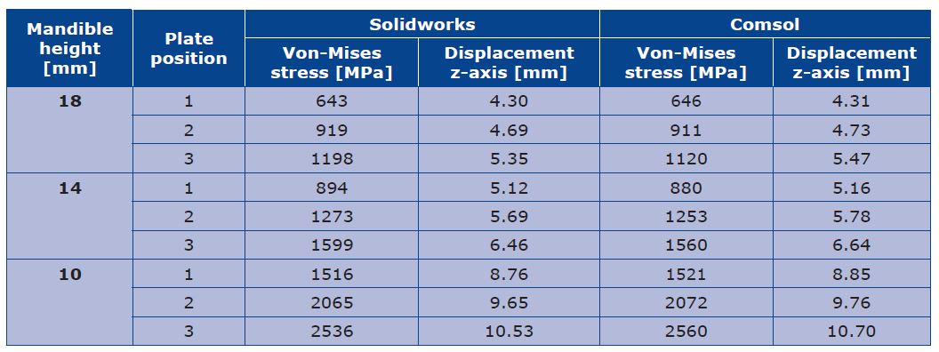
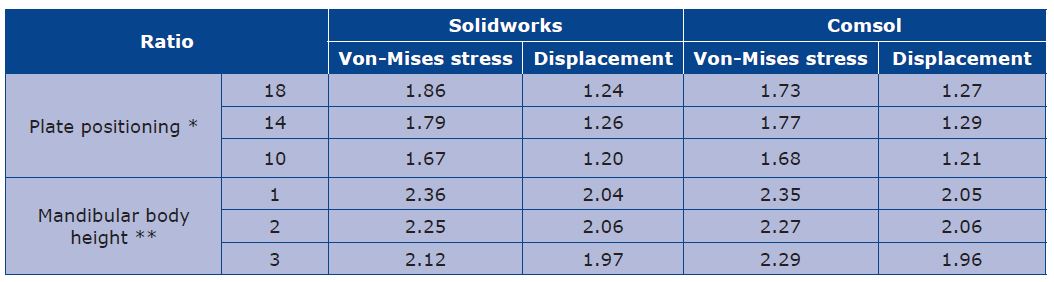
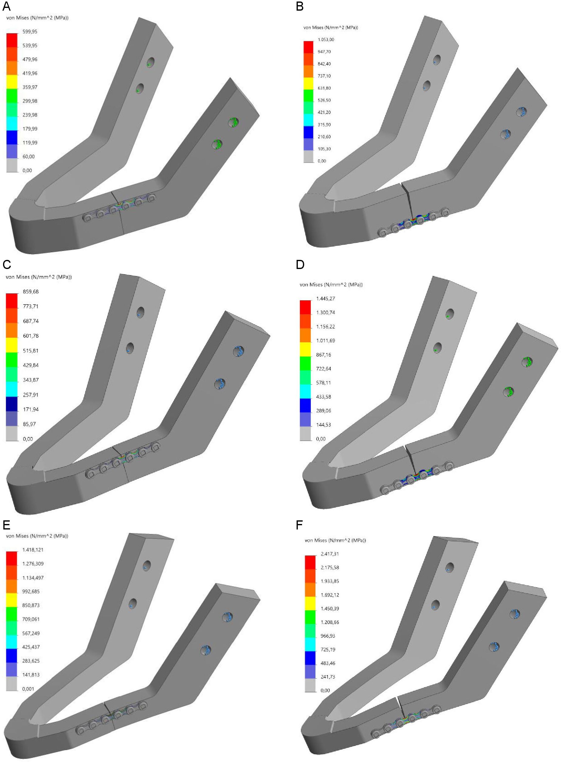
The results of the FEA are presented in Table 1, showing the maximum Von-Mises stress [MPa] and displacement [mm] outcomes. The maximum Von-Mises stress was located at the miniplates curvature between the third and the fourth screw holes, specifically at the edge of the plate where it was touching the mandibular body at the unilateral fracture site (Figure 5A-F). The table shows that stress and displacement increased with a decrease in mandibular body height. The same applies to when the miniplate was lowered from the mandibular upper border towards the lower border along the fracture line. The ratio of the Von-Mises stress and the ratio of the displacement in relation to plate positioning (miniplate at the lower border versus the upper border) and mandibular body height (10 mm versus 18 mm) are presented in Table 2. Observing the fracture surfaces shows that when the miniplate was positioned at the upper border, the fractures remained closed, intact, and stable. This was due to the tension zone at the upper border of the mandible and the compression zone at the lower border. However, when the miniplate was lowered, particularly when positioned at the lower border, the fracture surfaces tended to open from the upper border in a wedge-shaped form. In this situation the fixation was unstable (Figure 5).
Figure 5. FEA Von-Mises stress [MPa]: (A-B) 18 mm height mandible, (C-D) 14 mm height mandible, and (E-F) 10 mm height mandible; note: plate positioned at the upper border (right) and plate positioned at the lower border of the mandible (left)
FEA Comsol
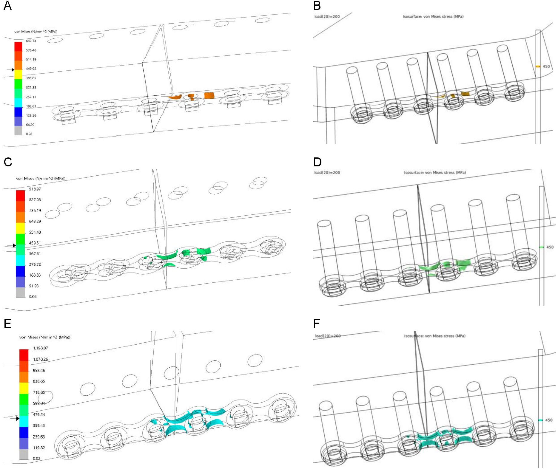
Comsol was used to check the reproducibility and accuracy of the Solidworks simulations. The Von-Mises stress [MPa] and displacement [mm] are shown in Table 1. The maximum stress location according to Comsol was identical to all the Solidworks FEA outcomes, namely at the edge of the plate where it was touching the mandibular body at the unilateral fracture site (Figure 5). The Von-Mises stress pattern comparison illustrates that the stress pattern remained identical in both FEA simulations at any selected stress point (Figure 6). This demonstrates that the Solidworks FEA outcomes are reproducible, accurate and correct. Furthermore, the Von-Mises stress ratio and the displacement ratio for the plate positioning and mandibular body height were similar to those generated in Solidworks (Table 2).
Figure 6. Comparison of Von-Mises stress between Solidworks (right) and Comsol (left) at 450 MPa for the 18 mm mandible height: (A-B) plate positioned at the upper border, (C-D) in the middle, and (E-F) at the lower border of the mandible
Table 1. FEA outcomes in Solidworks and Comsol regarding the maximum Von-Mises stress and displacement
Plate position: (1) upper border, (2) middle, and (3) lower border of the mandible. The z-axis was in the same direction as the applied 200 [N] force.
Table 2. Ratio of the Von-Mises stress [MPa] and displacement [mm] (Z-axis) for plate positioning and mandibular body height
* Ratio of the miniplate positioned at the lower border compared to the upper border for the 18, 14 and 10 mm mandibular body heights.
** Ratio between the 10 mm versus the 18 mm mandibular body heights for the plates positioned at the upper (1), in the middle (2) and the lower borders (3).
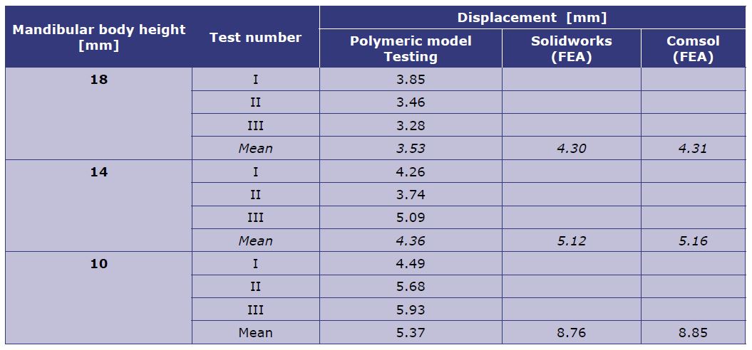
Table 3. Polymeric model testing displacement at 200 N compared to FEA displacement
All the test numbers (Test Number I-III) were done under the same conditions as miniplate located on the mandibular upper border. Italics: the mean polymeric model displacement (average test I-III) compared to the FEA study’s displacement values.
Fixation location sensitivity test
Sensitivity test evaluations of the different fixation locations illustrated a change of less than 10% for the maximum stress and displacement values. However, no changes were observed in the stress or displacement distribution patterns, as they remained identical. Furthermore, the FEA outcomes for analysing the effect of different mandibular body heights and plate positioning remained identical with no changes observed for the different fixation locations (Supplementary Figure S2).
Polymeric model testing
The displacement outcomes of the polymeric model testing are displayed in Table 3, showing that a decrease in mandibular body height resulted in an increased displacement. This indicates that the probability of failure increases when the mandibular body height decreases. Furthermore, the polymeric testing patterns were similar to the FEA, namely: a decrease in mandibular body height increased the fixation instability leading to implant failure.
Outcomes comparison
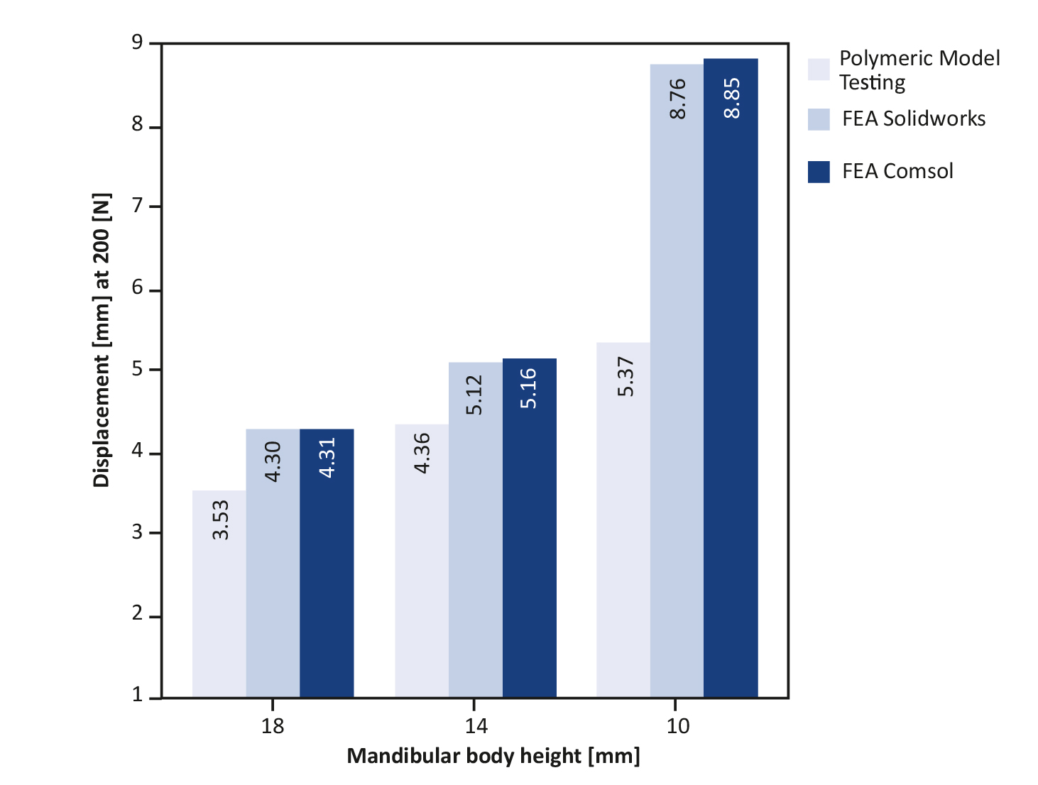
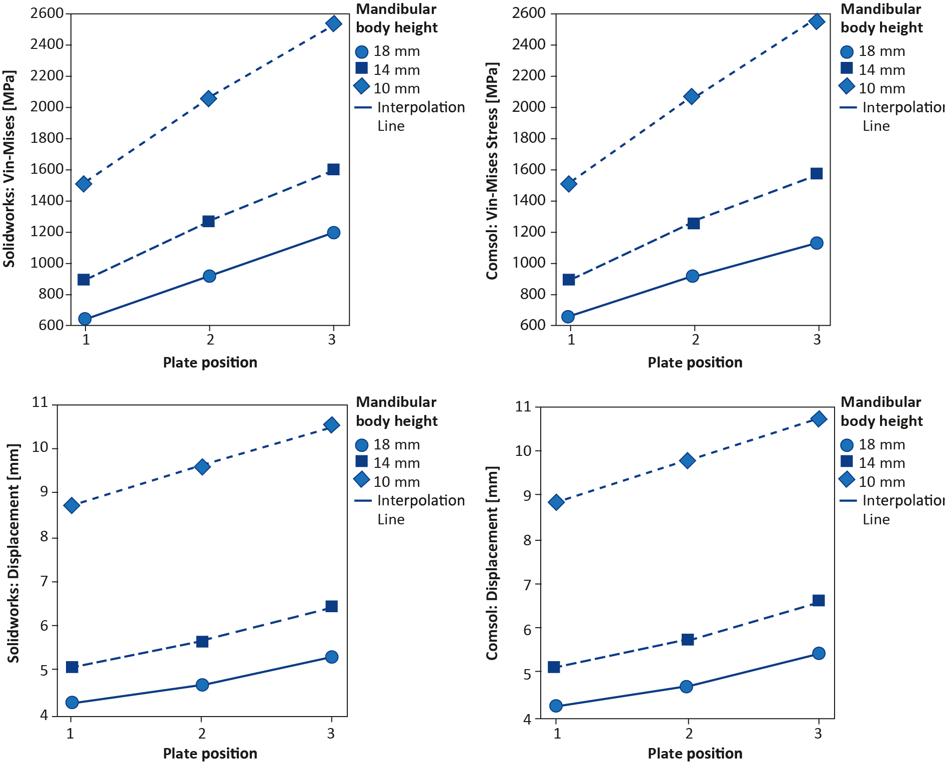
The FEA plots show that the Von-Mises stress (Figure 7A-B) and displacement (Figure 7C-D) increased with a decrease in mandibular body height. The same applies when the miniplate was lowered from the mandibular upper border towards the lower border along the fracture line (Figure 7). The maximum Von-Mises stress location at any selected stress point was similar in both simulation software (Figure 6). Furthermore, Figure 8 shows the 200 N displacement comparisons between the FEA and polymeric model testing, where displacement increased with a decrease in mandibular body height. Both the FEA simulations and polymeric model testing illustrated a similar pattern: a decrease in height resulted in an increase in displacement (Figure 8). Finally, the FEA outcomes were similar and highly comparable with those from the polymeric model testing.
Figure 7. (A-B) FEA Von-Mises stress plots: (A) Solidworks and (B) Comsol; (C-D) FEA displacement plots: (C) Solidworks and (D) Comsol
Figure 8. Displacement comparison between polymeric model testing and FEA at 200 N; the displacements are in the z-axis; the same direction as the applied mastication force.
Discussion
According to the literature, FEA has been a promising applicable tool in OMF surgery to analyse different types of fracture management and osteosynthesis implants [20-24, 35].
The outcomes of our study are consistent with some of the data that can be found in the literature. According to Tams et al. plate positioning is a crucial factor for mandibular fracture fixation stability [9]. Lowering the plate along the fracture line from the mandibular upper border toward the lower border decreases the fracture fixation stability. Therefore, locating the plate on the upper border results in better stability, even with small plates. Based on Champy et al., upper border plate placement is based on the fact that mastication creates a tensile force in the upper border and a compression force at the lower border resulting in the closure of the fracture (Figure 5) [8]. This study’s FEA simulation results are similar, whereby the Von-Mises stress and displacement increase when the plate is moved along the fracture line from the upper border towards the lower border of the mandibular body (Table 1, Figure 7).
According to Ellis et al. and Gerbino et al., the mandibular body height significantly affects fracture fixation stability [36-37]. A decrease in mandibular height increases fracture fixation instability [38]. It is more difficult to achieve fixation stability with a miniplate in the atrophic mandible than in cases with a normal mandibular height. In terms of stability, it means that a miniplate that does well in slightly or moderately atrophied mandibles (18 or 14 mm height) and performs poorly in severely atrophic mandibles (10 mm) (Table 2). The literature suggests several solutions for instability in the management of mandibular fractures with decreased height: e.g. thicker plates and/or more screws at each side of the fracture [36-38].
We used the polymeric model testing method to verify the FEA simulation outcomes. They both showed that displacement increases when the mandibular body height decreases (Table 3, Figure 8). This is in line with the literature [5, 8, 37] and the current clinical observation. This suggests that both FEA studies are good models for analysing mandibular fractures. Furthermore, the polymeric model testing outcomes indicate that using a 6-hole miniplate is not sufficient for lower mandibular height fracture management. It is plausible that a 4-hole miniplate would have performed even worse in this case. Therefore, 10 mm or lower mandibular height fracture fixation requires a stronger osteosynthesis system. In this case, the load-sharing principle is not valid and the load-bearing principle should be applied [6-7].
There are some limitations regarding the polymeric model testing. Namely, only displacement outcomes in the Z-axis (the same direction as the applied force) could be compared between the polymeric tests and the FEA studies. This is because the mechanical test bench used in this study could only calculate the displacement as the output result. Furthermore, the displacement values between the FEA studies compared to polymeric model testing were not exactly similar (Table 3) due to: (1) the shape of mandibles (the geometrical shapes of the polymeric models were similar to human mandibles, whereas the FEA mandibles were simplified models to eliminate mesh errors, (2) FEA uses numerical simulation to calculate the amount of displacement. However, on the mechanical test bench, displacement was measured based on the movement of the loading bar from the predetermined zero position to the end position where the mandible fractured or fixation failed. Nevertheless, the displacement results from the FEA studies and polymeric model testing are highly comparable (Table 3, Figure 8).
Finally, our FEA and polymeric model testing outcomes are similar and comparable with earlier studies [1-9, 19]. The similar displacement patterns of the FEA and polymeric model testing, together with the comparability with earlier studies [6-9, 36-38], show that our study was conducted correctly.
The outcomes of the 3D simulation software programs were similar and comparable (Table 1 and 2) including stress and displacement patterns (Figure 6 and 7). This indicates that the FEA setup and outcomes are reproducible and correct. The minor differences in the Solidworks and Comsol outcome values are caused by the inherent differences in the computational calculations in the 3D simulation environments of both software.
Currently we are working on improving our current mandible model by developing a 3D computer model based on the exact geometrical shape of the mandible instead of using a simplified version, as we did in this study. An approachable method for 3D mandible modelling is being designed based on CT images. We believe that the FEA approach could significantly help the surgeon by giving a better understanding of the preferred fracture management regime via creating a 3D visualisation of the fracture, guiding towards an optimal reposition approach and enabling the selection of the most suitable fixation technique. Regarding complex fracture cases (e.g. comminuted or atrophic mandibles), FEA could be applied to design a patient-specific osteosynthesis system. To achieve this, we are analysing other types of mandibular fractures (e.g. angle, symphysis or parasymphysis) based on the FEA simulation and polymeric model testing validation. The model should help the surgeon to optimise mandibular fracture treatment, thereby improving the surgical practice and the clinical outcome. It is possible the same FEA methodology approach can be used for optimisation of other bone fractures. However, extensive model testing is necessary to validate whether FEA can be used to test other kinds of fracture management. Such studies could determine whether FEA alone is sufficient to optimise surgical fracture management.
Conclusions
This study illustrates that FEA is a promising applicable tool for simulating various types of fractures and fixation systems in OMF surgery. It can be applied in the clinical setting for fracture management. FEA can provide clinicians with a lot of information regarding the selection of suitable osteosynthesis and the positioning of the plate concerning fracture fixation stability. This is achieved by evaluating the biomechanical behaviour between the plate and the fracture (e.g. stress, displacement, and forces). Further, FEA provides a clear visualisation of what could be expected in terms of fracture stability.
Funding
None
Conflicts of interest
None
-----
Supplementary Figure S1. FEA Von-Mises stress [MPa] for different fixation location: (A-B) 18 mm height mandible, (C-D) 14 mm height mandible, and (E-F) 10 mm height mandible; note: plate positioned at the upper border (right) and plate positioned at the lower border of the mandible (left)
Supplementary Figure S2. Mesh convergence plots: (A) 18 mm height mandible, (B) 12 mm height mandible, and (C) 10 mm height mandible
References
| 1. |
Gareb B, Roossien CC, van Bakelen NB, Verkerke GJ, Vissink A, Bos RRM, et al. Comparison of the mechanical properties of biodegradable and titanium osteosynthesis systems used in oral and maxillofacial surgery. Sci Rep. 2020;10(1):18143. Available from: http://www.ncbi.nlm.nih.gov/pubmed/33097757.
|
| 2. |
Payan Y, Chabanas M, Pelorson X, Vilain C, Levy P, Luboz V, et al. Biomechanical models to simulate consequences of maxillofacial surgery. C R Biol. 2002;325(4):407-17. Available from: https://linkinghub.elsevier.com/retrieve/pii/S1631069102014439.
|
| 3. |
Wong RCW, Tideman H, Merkx MAW, Jansen J, Goh SM, Liao K. Review of biomechanical models used in studying the biomechanics of reconstructed mandibles. Int J Oral Maxillofac Surg. 2011;40(4):393-400. Available from: https://linkinghubelsevier.com/retrieve/pii/S0901502710005217.
|
| 4. |
Buijs GJ, van Bakelen NB, Jansma J, de Visscher JGAM, Hoppenreijs TJM, Bergsma JE, et al. A randomized clinical trial of biodegradable and titanium fixation systems in maxillofacial surgery. J Dent Res. 2012;91(3):299-304. Available from: http://journals.sagepub.com/doi/10.1177/0022034511434353.
|
| 5. |
Bohner L, Beiglboeck F, Schwipper S, Lustosa R, Pieirna Marino Segura C, Kleinheinz J, et al. Treatment of mandible fractures using a miniplate system: a retrospective analysis. J Clin Med. 2020;9(9):2922. Available from: https://www.mdpi.com/2077-0383/9/9/2922.
|
| 6. |
Haerle F, Champy M, Terry BC. Atlas of craniomaxillofacial osteosynthesis. Second. Haerle F, Champy M, Terry BC, Reinhardt A, editors. Stuttgart: Georg Thieme Verlag; 2009. Available from: http://www.thieme-connect.de/products/ebooks/book/10.1055/b-002-72255.
|
| 7. |
Prein J, Ehrenfeld M, Manson PN. Principles of internal fixation of the craniomaxillofacial skeleton. Ehrenfeld M, Manson PN, Prein J, editors. Stuttgart: Georg Thieme Verlag; 2012. Available from: http://www.thiemeconnect.de/products/ebooks/ book/10.1055/b-002-85491.
|
| 8. |
Champy M, Lodde JP. [Mandibular synthesis. Placement of the synthesis as a function of mandibular stress]. Rev Stomatol Chir Maxillofac. 1976;77(8):971-6. Available from: http://www.ncbi.nlm.nih.gov/pubmed/1071237.
|
| 9. |
Tams J, van Loon J-P, Otten E, Rozema FR, Bos RRM. A three-dimensional study of bending and torsion moments for different fracture sites in the mandible: an in vitro study. Int J Oral Maxillofac Surg. 1997;26(5):383-8. Available from: https://linkinghub.elsevier.com/retrieve/pii/S090150279780803X.
|
| 10. |
Franciosi E, Mazzaro E, Larranaga J, Rios A, Picco P, Figari M. Treatment of edentulous mandibular fractures with rigid internal fixation: case series and literature review. Craniomaxillofac Trauma Reconstr. 2014;7(1):35-41. Available from: http://journals.sagepub.com/doi/10.1055/s-0033-1364195.
|
| 11. |
Batbayar EO, Bos RRM, van Minnen B. A treatment protocol for fractures of the edentulous mandible. J Oral Maxillofac Surg. 2018;76(10):2151-60. Available from: https://linkinghub.elsevier.com/retrieve/pii/S027823911830329X.
|
| 12. |
Brucoli M, Boffano P, Romeo I, Corio C, Benech A, Ruslin M, et al. Surgical management of unilateral body fractures of the edentulous atrophic mandible. Oral Maxillofac Surg. 2020;24(1):65-71. Available from: http://link.springer.com/10.1007/s10006-019-00824-8.
|
| 13. |
Goh BT, Lee S, Tideman H, Stoelinga PJW. Mandibular reconstruction in adults: a review. Int J Oral Maxillofac Surg. 2008;37(7):597-605. Available from: https://linkinghub.elsevier.com/retrieve/pii/S0901502708000933.
|
| 14. |
Emam HA, Ferguson HW, Jatana CA. Management of atrophic mandible fractures: an updated comprehensive review. Oral Surg. 2018;11(1):79-87. Available from: https://onlinelibrary.wiley.com/doi/10.1111/ors.12300.
|
| 15. |
Sukegawa S, Kanno T, Masui M, Sukegawa-Takahashi Y, Kishimoto T, Sato A, et al. A retrospective comparative study of mandibular fracture treatment with internal fixation using reconstruction plate versus miniplates. J Cranio-Maxillofacial Surg. 2019;47(8):1175-80. Available from: https://linkinghub.elsevier.com/retrieve/pii/S101051821830204X.
|
| 16. |
Sittitavornwong S, Denson D, Ashley D, Walma DC, Potter S, Freind J. Integrity of a single superior border plate repair in mandibular angle fracture: a novel cadaveric human mandible model. J Oral Maxillofac Surg. 2018;76(12):2611.e1-2611.e8. Available from: https://linkinghub.elsevier.com/retrieve/pii/S0278239118308504.
|
| 17. |
Huang CM, Chan MY, Hsu JT, Su KC. Biomechanical analysis of subcondylar fracture fixation using miniplates at different positions and of different lengths. BMC Oral Health 2021;21(1):543. Available from: https://bmcoralhealth.biomedcentral.com/articles/10.1186/s12903-021-01905-5.
|
| 18. |
Trainotti S, Raith S, Kesting M, Eichhorn S, Bauer F, Kolk A, et al. Locking versus nonlocking plates in mandibular reconstruction with fibular graft – a biomechanical ex vivo study. Clin Oral Investig. 2014;18(4):1291-8. Available from: http://link.springer.com/10.1007/s00784-013-1105-1.
|
| 19. |
Hart RT, Hennebel V V., Thongpreda N, Van Buskirk WC, Anderson RC. Modeling the biomechanics of the mandible: A three-dimensional finite element study. J Biomech. 1992 ;25(3):261-86. Available from: https://linkinghub.elsevier.com/retrieve/pii/002192909290025V.
|
| 20. |
Anthrayose P, Nawal RR, Yadav S, Talwar S, Yadav S. Effect of revascularisation and apexification procedures on biomechanical behaviour of immature maxillary central incisor teeth: a three-dimensional finite element analysis study. Clin Oral Investig. 2021;25(12):6671-9. Available from: https://link.springer.com/10.1007/s00784-021-03953-1.
|
| 21. |
Patussi C, Sassi LM, Cruz R, Klein Parise G, Costa D, Rebellato NLB. Evaluation of different stable internal fixation in unfavorable mandible fractures under finite element analysis. Oral Maxillofac Surg. 2019;23(3):317-24. Available from: http://link.springer.com/10.1007/s10006-019-00774-1.
|
| 22. |
Limjeerajarus N, Dhammayannarangsi P, Phanijjiva A, Tangsripongkul P, Jearanaiphaisarn T, Pittayapat P, et al. Comparison of ultimate force revealed by compression tests on extracted first premolars and FEA with a true scale 3D multi-component tooth model based on a CBCT dataset. Clin Oral Investig. 2020;24(1):211-20. Available from: http://link.springer. com/10.1007/s00784-019-02919-8.
|
| 23. |
Merema BBJ, Kraeima J, Glas HH, Spijkervet FKL, Witjes MJH. Patient – specific finite element models of the human mandible: Lack of consensus on current setups. Oral Dis. 2021;27(1):42-51. Available from: https://onlinelibrary.wiley.com/doi/10.1111/odi.13381.
|
| 24. |
Lisiak-Myszke M, Marciniak D, Bieliński M, Sobczak H, Garbacewicz Ł, Drogoszewska B. Application of finite element analysis in oral and maxillofacial surgery – a literature review. Materials (Basel) 2020;13(14):3063. Available from: https://www.mdpi.com/1996-1944/13/14/3063.
|
| 25. |
Daas M, Dubois G, Bonnet AS, Lipinski P, Rignon-Bret C. A complete finite element model of a mandibular implant-retained overdenture with two implants: Comparison between rigid and resilient attachment configurations. Med Eng Phys. 2008;30(2):218-25. Available from: https://linkinghub.elsevier.com/retrieve/pii/S1350453307000379.
|
| 26. |
Ammar HH, Ngan P, Crout RJ, Mucino VH, Mukdadi OM. Three-dimensional modeling and finite element analysis in treatment planning for orthodontic tooth movement. Am J Orthod Dentofac Orthop. 2011;139(1):e59-71. Available from: https://linkinghub.elsevier.com/retrieve/pii/S0889540610008061.
|
| 27. |
Novelli G, Sconza C, Ardito E, Bozzetti A. surgical treatment of the atrophic mandibular fractures by locked plates systems: our experience and a literature review. Craniomaxillofac Trauma Reconstr. 2012;5(2):65-74. Available from: http://journals.sagepub.com/doi/10.1055/s-0031-1300961.
|
| 28. |
Schupp W, Arzdorf M, Linke B, Gutwald R. Biomechanical testing of different osteosynthesis systems for segmental resection of the mandible. J Oral Maxillofac Surg. 2007;65(5):924-30. Available from: https://linkinghub.elsevier.com/retrieve/pii/S0278239107001279.
|
| 29. |
Kumar S, Sankhla B, Garg A, Dagli N, Gattumeedhi S, Ingle E. Comparative evaluation of bite forces in patients after treatment of mandibular fractures with miniplate osteosynthesis and internal locking miniplate osteosynthesis. J Int Soc Prev Community Dent. 2014;4(4):26. Available from: http://www.jispcd.org/text.asp?2014/4/4/26/144575.
|
| 30. |
Brown AD, Walters JB, Zhang YX, Saadatfar M, Escobedo-Diaz JP, Hazell PJ. The mechanical response of commercially available bone simulants for quasi-static and dynamic loading. J Mech Behav Biomed Mater. 2019;90:404-16. Available from: https://linkinghub.elsevier.com/retrieve/pii/S1751616118307458.
|
| 31. |
Park Y-C, Chae D-S, Kang K-Y, Ding Y, Park S-J, Yoon J. Comparative pull-out performances of cephalomedullary nail with screw and helical blade according to femur bone densities. Appl Sci. 2021;11(2):496. Available from: https://www.mdpi.com/2076-3417/11/2/496.
|
| 32. |
Haug RH, Peterson GP, Goltz M. A biomechanical evaluation of mandibular condyle fracture plating techniques. J Oral Maxillofac Surg. 2002;60(1):73-80. Available from: https://linkinghub.elsevier.com/retrieve/pii/S0278239102346408.
|
| 33. |
Bredbenner TL, Haug RH. Substitutes for human cadaveric bone in maxillofacial rigid fixation research. Oral Surgery, Oral Med Oral Pathol Oral Radiol Endodontology 2000;90(5):574-80. Available from: https://linkinghub.elsevier.com/retrieve/pii/S1079210400094610.
|
| 34. |
Aymach Z, Nei H, Kawamura H, Bell W. Biomechanical evaluation of a T-shaped miniplate fixation of a modified sagittal split ramus osteotomy with buccal step, a new technique for mandibular orthognathic surgery. Oral Surgery, Oral Med. Oral Pathol Oral Radiol Endodontology 2011;111(1):58-63. Available from: https://linkinghub.elsevier.com/retrieve/pii/S1079210410002052.
|
| 35. |
Park B, Jung BT, Kim WH, Lee J-H, Kim B, Lee J-H. The stability of hydroxyapatite/Poly-L-lactide fixation for unilateral angle fracture of the mandible assessed using a finite element analysis model. Materials (Basel) 2020;13(1):228. Available from: https://www.mdpi.com/1996-1944/13/1/228.
|
| 36. |
Ellis E, Price C. Treatment protocol for fractures of the atrophic mandible. J Oral Maxillofac Surg. 2008;66(3):421-35. Available from: https://linkinghub.elsevier.com/retrieve/pii/S0278239107019453.
|
| 37. |
Gerbino G, Cocis S, Roccia F, Novelli G, Canzi G, Sozzi D. Management of atrophic mandibular fractures: An Italian multicentric retrospective study. J Cranio-Maxillofacial Surg [Internet]. 2018;46(12):2176-81. Available from: https://linkinghub.elsevier.com/retrieve/pii/S1010518218301963.
|
| 38. |
Sugiura T, Yamamoto K, Murakami K, Kawakami M, Kang Y-B, Tsutsumi S, et al. Biomechanical Analysis of miniplate osteosynthesis for fractures of the atrophic mandible. J Oral Maxillofac Surg. 2009;67(11):2397-403. Available from: https://linkinghub.elsevier.com/retrieve/pii/S0278239108015127.
|
